
Understand the essential principles of the digital electronics topic titled “4.8 Logic Gates: Truth Tables in Digital Electronics”. This area is fundamental for IT systems and enables in designing electronic systems.
A detailed overview is presented below:
1. Introduction
In the realm of digital electronics, logic gates serve as fundamental building blocks for designing and implementing digital systems. These gates perform logical operations that process binary signals, enabling complex decision-making and data processing tasks. Understanding the concept of truth tables is essential for deciphering how logic gates function, as they meticulously outline the relationship between inputs and outputs. This knowledge is crucial across various technological domains, including banking automation systems where secure transactions depend on these logical operations, embedded systems that rely on logic gates for control functions, and broader IT applications involving data processing and hardware logic design. Mastery of truth tables facilitates a clear comprehension of circuit behavior, simplifies troubleshooting, and aids in designing efficient digital circuits. For aspiring IT and System Officers, grasping the principles of logic gates and their truth tables forms the backbone of understanding digital system architecture and operation.
2. Core Concept
2.1 Definition
- Logic Gates: Electronic circuits that perform basic logical functions, producing a single output based on one or more binary inputs.
- Truth Tables: Tabular representations that show how the output of a logic gate responds to every possible combination of inputs.
2.2 Working Principles
- Boolean Algebra: Logic gates operate based on Boolean algebra principles, where variables take binary values of 0 (false) or 1 (true).
- Input-Output Relationship: Each gate has specific rules determining its output for every input combination, systematically listed in the truth table.
- Gate Functionality: By combining different gates and their truth tables, complex digital circuits perform tasks such as arithmetic, data decoding, and decision-making.
2.3 Real-life Applications
- Computers and Microprocessors: Logic gates implement core computational functions in CPUs, influencing processing speed and efficiency.
- Digital Signal Processing: Used in filtering, modulation, and encoding processes that require logical decision-making.
- Security Systems: Logic gates underpin digital locks, alarm systems, and authentication devices in banking and corporate security.
- Embedded Systems: Control units in household appliances and automotive electronics often rely on logic gate circuits.
- Communication Devices: Modems and network routers utilize logic gates for signal routing and data management.
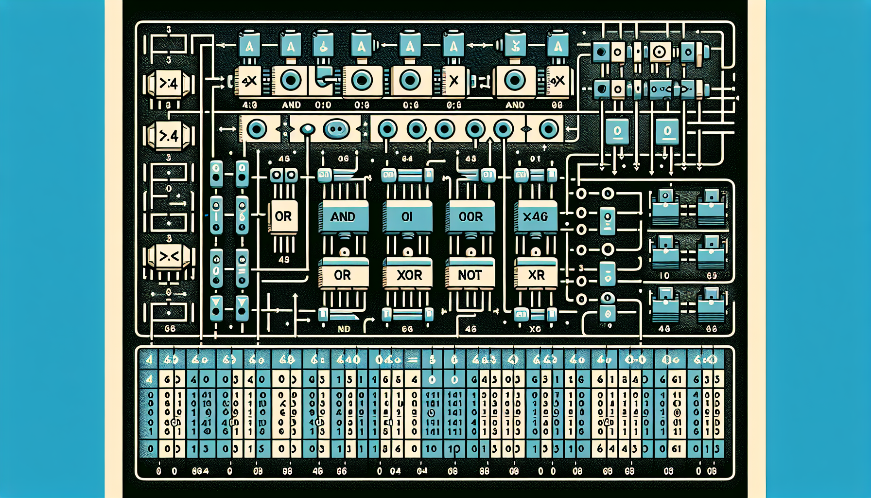
3. Diagrams and Visual Aids
3.1 Truth Tables
| Input A | Input B | Output |
|---|---|---|
| 0 | 0 | 0 |
| 0 | 1 | 1 |
| 1 | 0 | |
| 1 | 1 |
3.2 Karnaugh Maps
 K-Map for AND Gate:

    AB | 00 | 01 | 11 | 10 |

    -------------------------

        |  0 |  0 |  1 |  0 |
3.3 Circuit Layouts
AND Gate Circuit:

   A ----|>>----|>|

          |       |>|-- Output (A AND B)

   B ----|>|     |>|

                  |
3.4 Timing Diagrams
Input A:  ---|>-----|>-----|>-----

Input B:  ------|>--|>---|>------

Output (A AND B):

             _________
3.5 Conversion Charts
| Binary | Decimal | Hexadecimal |
|---|---|---|
| 0000 | 0 | 0 |
| 0001 | 1 | 1 |
| 0010 | 2 | 2 |
| 1111 | 15 | F |
4. Real-World Applications
- Banking ATMs: Logic circuits facilitate secure encryption and transaction verification.
- Microcontrollers in Embedded Devices: Logic gates enable control operations in smart appliances and automotive systems.
- Network Hardware: Routers and switches utilize logic to manage data routing and protocol execution.
- Security Systems: Digital locks and alarm systems depend on logic-based decision mechanisms.
- Digital Communication Devices: Logic gates support encoding, decoding, and signal processing in telecommunication hardware.
5. Important Formulas
- AND Operation:
Output = A & B
For inputs A and B, AND yields:

A B | Output

0 0 | 0

0 1 | 0

1 0 | 0

1 1 | 1
Output = A | B
A B | Output

0 0 | 0

0 1 | 1

1 0 | 1

1 1 | 1
Output = ¬A
A | ¬A

0 |  1

1 |  0
6. MCQs for Practice
Q1. What is the primary function of an AND gate?

A. To perform logical OR operation

B. To perform logical AND operation ✔️ Correct

C. To invert the input

D. To perform XOR operation
Q2. In a truth table for an OR gate, what is the output when both inputs are 0?

A. 0 ✔️ Correct

B. 1

C. Depends on the circuit

D. Cannot be determined
Q3. Which of the following gates produces a true output only when exactly one input is true?

A. AND

B. OR

C. XOR ✔️ Correct

D. NOR
Q4. The Boolean expression for a NAND gate is:

A. A & B

B. ¬ (A & B) ✔️ Correct

C. A | B

D. ¬A & ¬B
Q5. Which logic gate's truth table is shown below?

Input A | Input B | Output

0       | 0       | 1

0       | 1       | 1

1       | 0       | 1

1       | 1       | 0

A. NOR

B. NAND

C. XOR

D. NOR ✔️ Correct
Q6. What does the Karnaugh Map help optimize?

A. Power consumption

B. Circuit layout

C. Boolean expressions ✔️ Correct

D. Input signal strength
Q7. Which of the following is NOT a fundamental logic gate?

A. AND

B. OR

C. NOT

D. MULTIPLY ✔️ Correct
Q8. A circuit that produces an output only when both inputs are high is called:

A. AND gate ✔️ Correct

B. OR gate

C. NOT gate

D. XOR gate
Q9. Which gate provides an output of 0 only when both inputs are 1?

A. NAND

B. NOR

C. AND ✔️ Correct

D. XOR
Q10. The truth table for a NOT gate is:

A. 0 → 0, 1 → 1

B. 0 → 1, 1 → 0 ✔️ Correct

C. Both inputs are the same

D. It depends on the circuit design
7. Frequently Asked Questions (FAQs)
- Q: What is the most basic logic gate involved in digital electronics?
A: The AND gate is considered one of the fundamental logic gates, along with OR and NOT gates, forming the basis for complex digital circuits. - Q: How do truth tables help in designing digital circuits?
A: Truth tables provide a clear and systematic way to depict the behavior of logic gates, making it easier to analyze, simplify, and design digital logic circuits. - Q: Why is understanding Boolean algebra important in digital electronics?
A: Boolean algebra offers the mathematical framework to minimize and optimize logic circuits, crucial for efficient hardware design. - Q: Are truth tables applicable to multiple input gates?
A: Yes, truth tables can be extended to any number of inputs, although the size increases exponentially with each added input. - Q: What is the significance of Karnaugh maps in circuit design?
A: Karnaugh maps aid in simplifying Boolean expressions, leading to less complex and more cost-effective circuits. - Q: Can a combination of logic gates implement any digital function?
A: Yes, through combination and arrangement of basic gates, any logical function can be implemented in digital electronics.
8. Summary
- 4.8 Logic Gates: Truth Tables in Digital Electronics serve as fundamental tools to understand how digital circuits operate based on binary inputs.
- This knowledge is crucial because it forms the core of designing, analyzing, and troubleshooting digital systems used in fields like banking, embedded electronics, and IT hardware.
- Truth tables visually represent the input-output relationships of logic gates, providing clarity and aiding in circuit simplification.
- Various visual aids such as Karnaugh maps, circuit diagrams, and timing diagrams help in deeper understanding and practical application.
- Mastering Boolean algebra and truth table concepts is essential for students preparing for IT officer, system officer, and digital electronics exams, enabling effective circuit design.
9. Tags & Keywords
digital electronics, 4.8 Logic Gates: Truth Tables in Digital Electronics, logic gates, binary systems, IT officer exam, system officer, banking automation, electronics notes, circuit design
For more detailed study, refer to relevant textbooks,
official technical resources, or trusted educational sites.
Browse more related topics in our [Digital Electronics Archives](https://padhaiguru.in/category/digital-electronics/) for in-depth guides and notes.
Stay updated on digital electronics topics and exam tips using hashtags: #Logic #Gates #Truth #Tables #Digital #Electronics
Discuss your views about this topic in the comments below!
—
For further technical reference, see detailed entries on [Digital electronics fundamentals](https://en.wikipedia.org/wiki/Digital_electronics) and [Fundamental logic gate types](https://en.wikipedia.org/wiki/Logic_gate).
